


Project Overview
UCLA Bruin Supermileage — Hardware Technician
The Challenge
The Bruin Supermileage team engineers highly energy-efficient vehicles for competitive racing. Building an efficient vehicle requires managing complex mechanical assemblies—such as the steering system and brake box—and ensuring all custom-machined parts fit together perfectly to maintain structural integrity.
My Role: Hardware Team Technician
I joined this project specifically to expand my practical manufacturing and CAD skills. As a hardware technician, my primary focus was supporting the team with SolidWorks assembly modeling and gaining hands-on experience in the machine shop by cutting and assembling physical components for the vehicle.
Skills & Contributions
My contributions grouped naturally into CAD assembly support, CNC fabrication practice, and mechanical integration—documented below with both vehicle-specific photos from the club and two machining photos from my shop work on related aluminum components.
SolidWorks assemblies
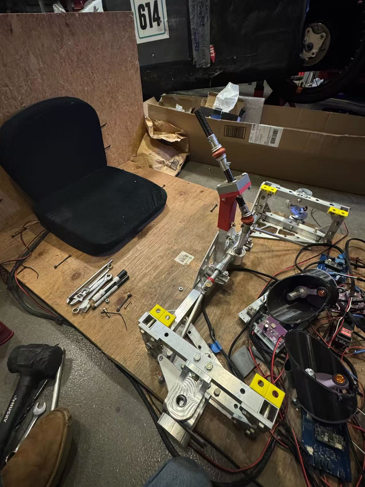
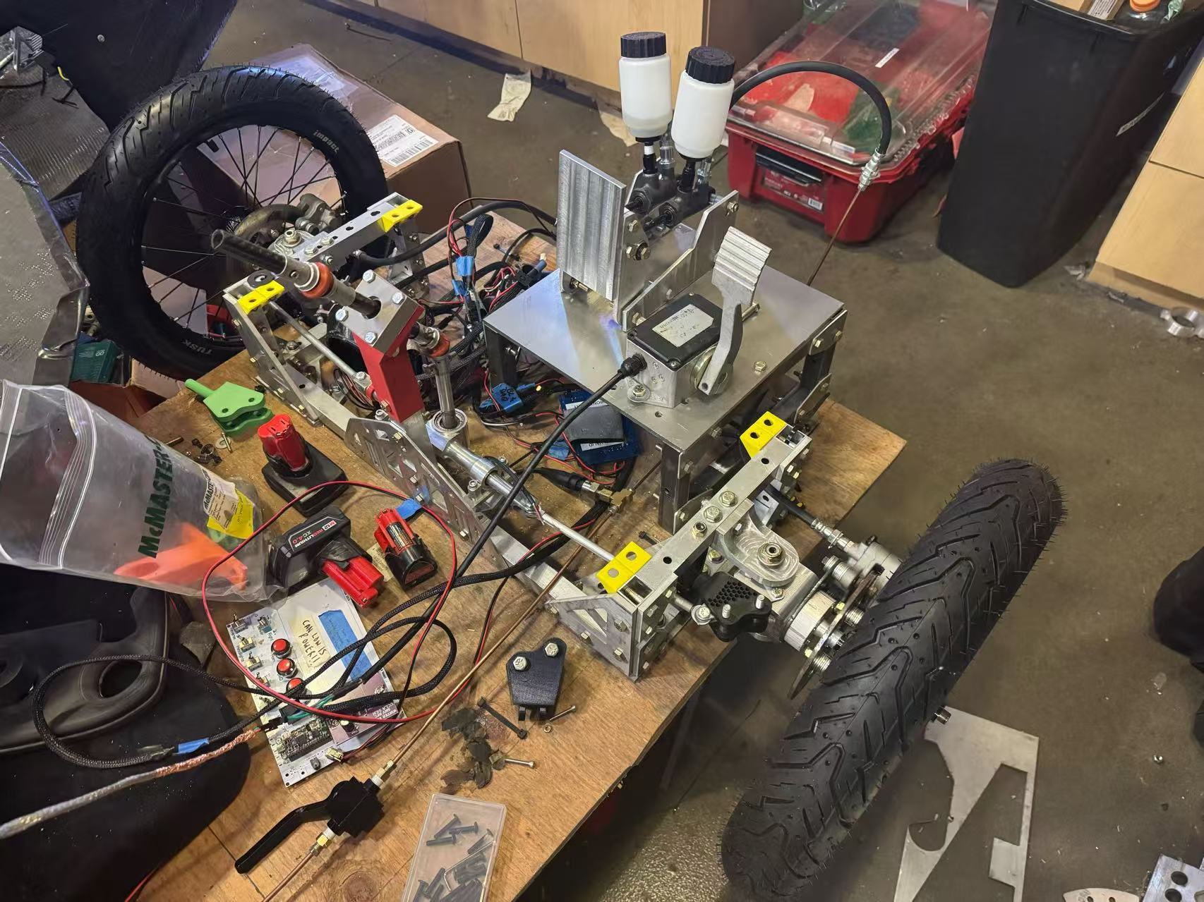
Steering hardware — assembly context on the vehicle
Steering & system-level fitment
Gained valuable experience working with complex, multi-part CAD files. I worked on the assemblies for the steering system and brake box, learning how to manage part fitment and clearances within a larger vehicle design.
Seeing the steering hardware installed clarified constraints that are easy to miss in isolation—clearance around suspension packaging, fastener access for repeated service, and how tie-in brackets load the frame when drivers saw aggressive steering inputs on track.
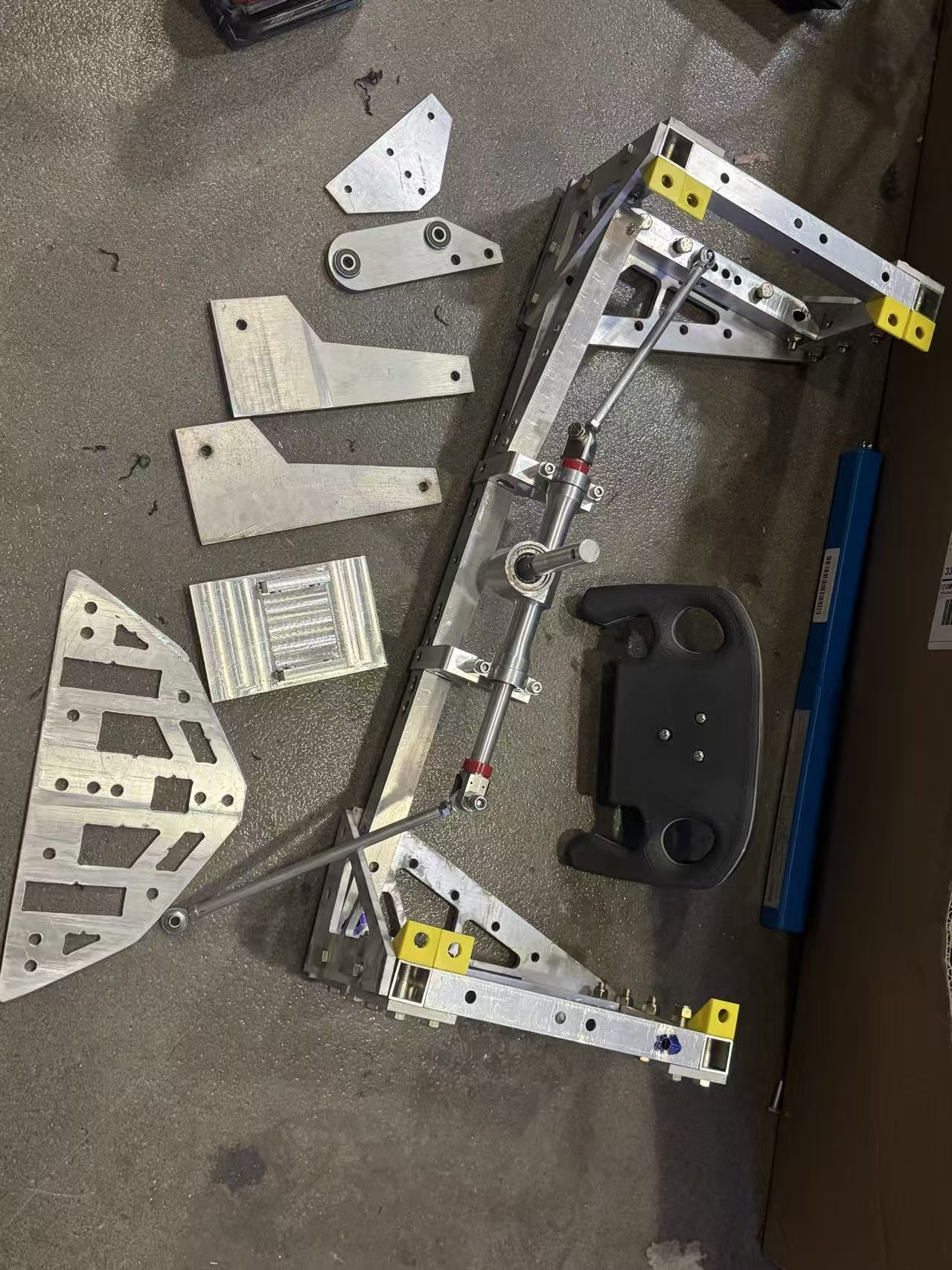
Steering assembly — alternate angle for routing and brackets
CAD ↔ hardware correspondence
Comparing the physical steering stack to the SolidWorks hierarchy helped me internalize how mates and subassembly boundaries translate to torque paths in reality—especially where bearings, clamps, and adjustable links had to stay coaxial through adjustment ranges.
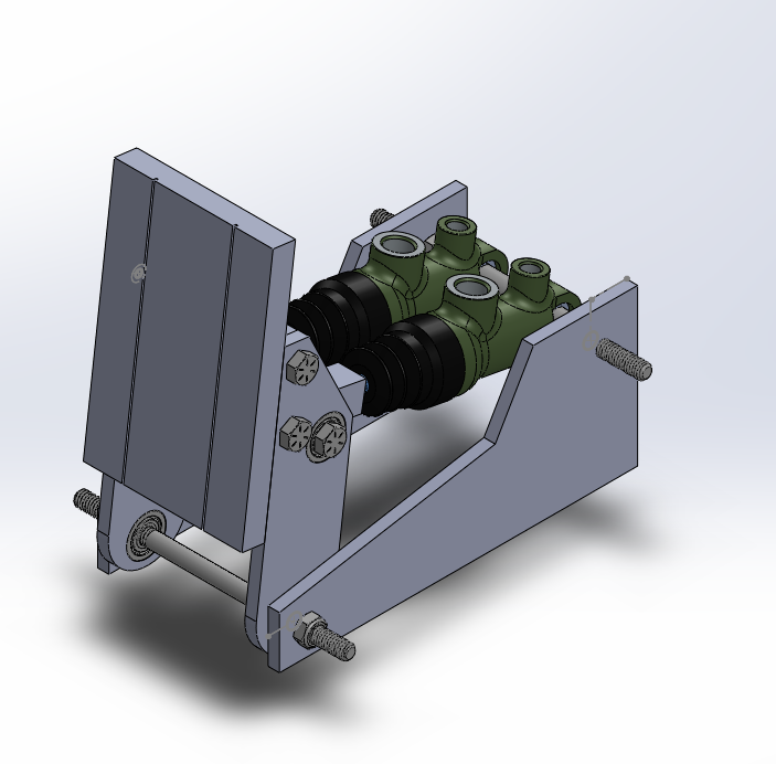
Brake box CAD (same overview as portfolio showcase above)
Brake box modeling focus
The brake box assembly was where multi-part tolerances stacked most visibly: bracket angles, fastener standoffs, and interface planes had to stay coherent so machined plates bolted up without introducing unintended moments into thin aluminium sections.
Introduction to CNC machining
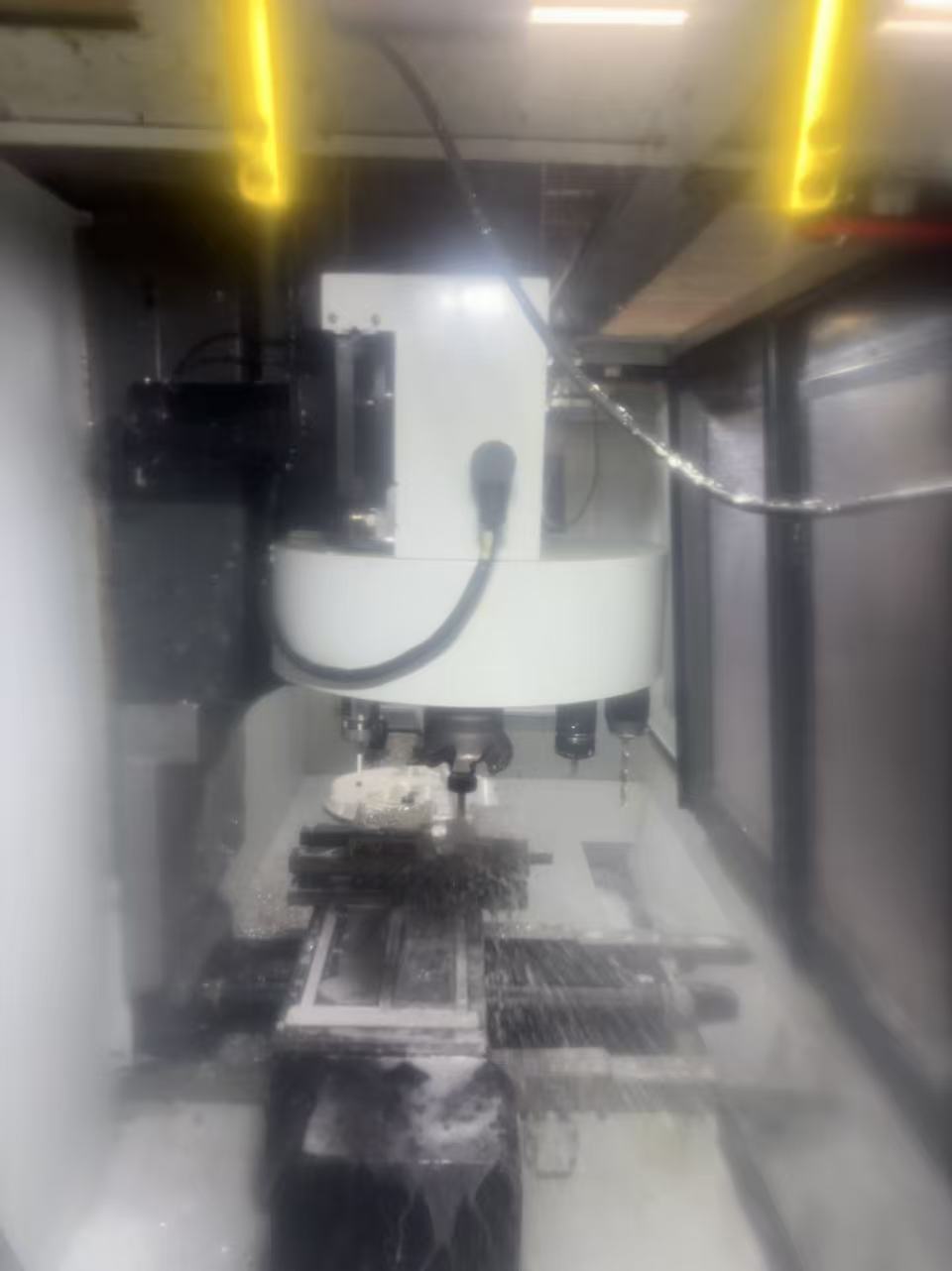
CNC machining — setup, cutting, and detail passes on aluminum
From CAD to chips
Used this project as an opportunity to learn the fundamentals of CNC machining. I assisted in fabricating custom aluminum parts, bridging the gap between digital CAD models and physical manufacturing.
Working next to experienced machinists taught workflow habits that CAD alone cannot: tool engagement on thin walls, workholding strategy so setups stayed repeatable across batches, and how to leave sensible finishing stock before moving parts to assembly.
Repeat cuts on scrap and witness coupons mattered as much as final geometry: verifying that measured dimensions tracked CAD within what the stack-up allowed once brackets met welded or bonded joints on the chassis.
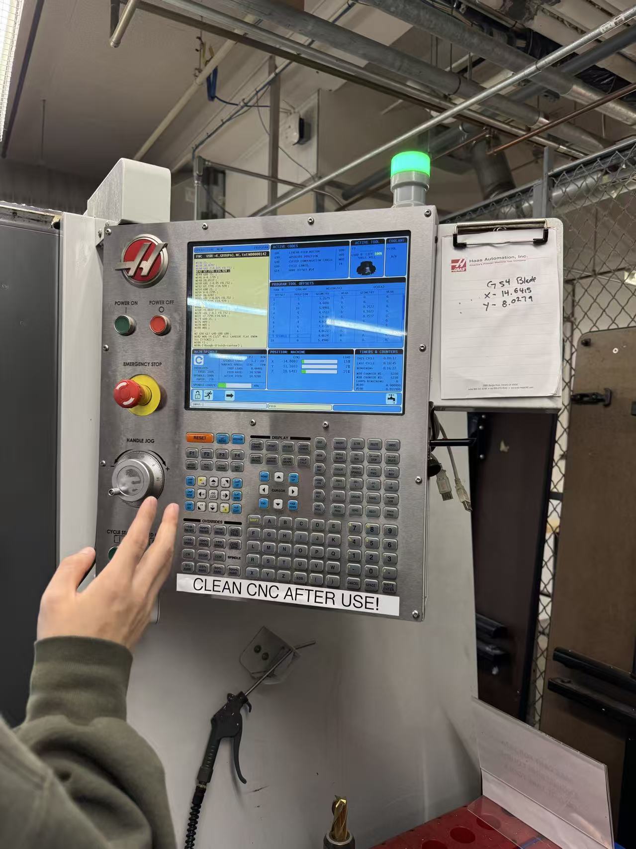
Machine shop — controls and safety during cuts
Safe, intentional feeds & speeds
Operating within the shop’s safety culture meant pairing conservative feeds with fixture checks—especially when balancing visibility against guarding while profiling complex perimeter contours on lightweight plates.
Hardware assembly & integration
Brake box assembly — hardware stage 1
Brake box integration
Assisted with the physical assembly and integration of the steering hardware and brake box, working alongside teammates to ensure the mechanical systems were put together securely and functioned as intended.
At this stage the CAD assumptions met hardware reality: shim stacks, torque sequences, and careful alignment of hydraulic or mechanical interfaces prevented leaks and binding when we exercised the system off the vehicle before final installation.

Brake box assembly — continuation & bracket interfaces
Interfaces & load paths
Integrating brackets that tied the brake box structure back to the chassis rails forced disciplined torque practices—especially where aluminium threads carried shear-adjacent reactions we did not want to gall during maintenance intervals.

Brake box assembly — near-complete integration check
Function checks before vehicle install
Before bolting systems into their final positions on the streamlined shell, we verified motion ranges and clearance envelopes under worst-case articulation—closing the loop between fabrication tolerances and the vehicle-level packaging constraints Supermileage racing demands.