


Project Overview
Dexterous Hand Research & Sensing
The Challenge
The initial objective of this research project was to develop a highly dexterous, multi-DOF humanoid robotic hand. However, to accurately replicate human dexterity, we first needed to collect precise kinematic data on how human finger joints move. This required us to pivot and build a custom wearable data collection device to track joint movements, as well as a highly accurate tactile sensor measurement system to evaluate contact forces and feedback.
My Role: Hardware & Research Lead
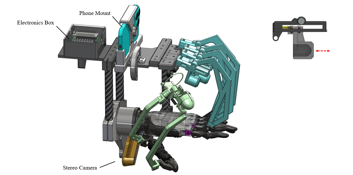
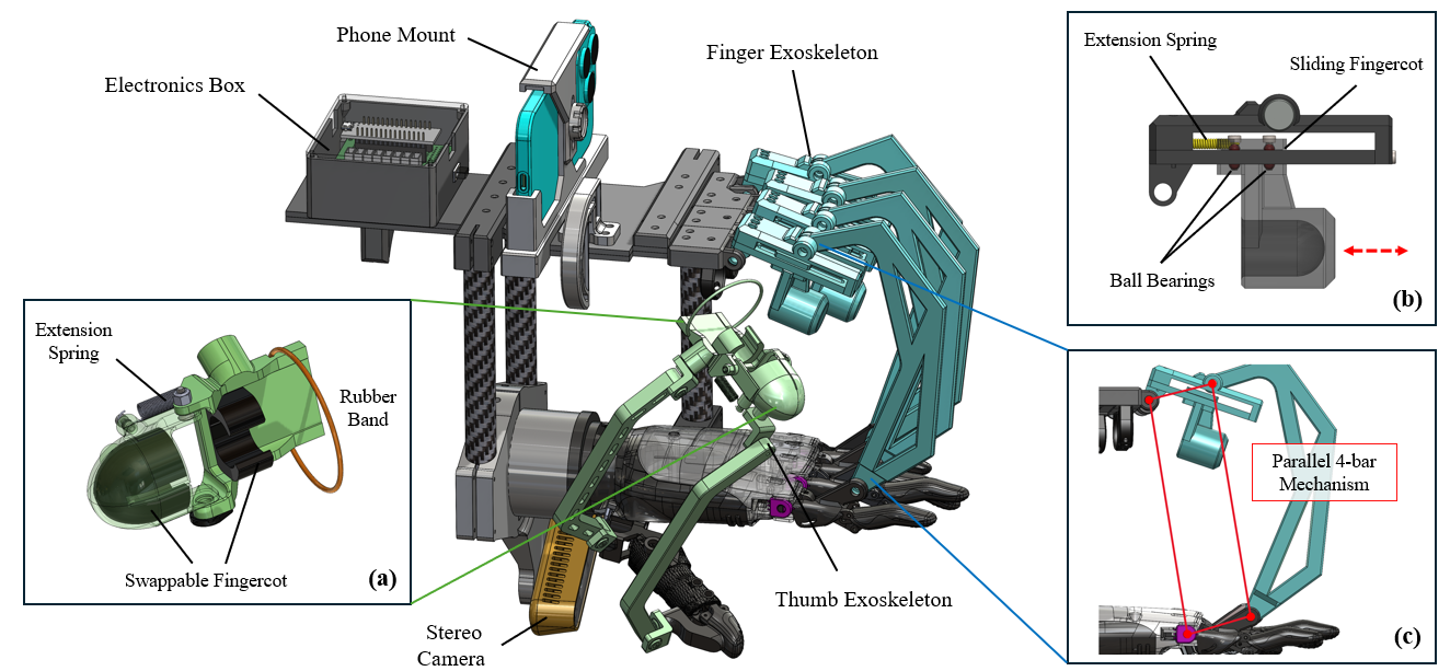
As an Undergraduate Researcher at RoMeLa, I spearheaded the benchmarking of existing commercial robotic hands, studying their complex assemblies to inform our own 19-DOF mechanical architecture. I also managed the hands-on fabrication, taking charge of the electrical soldering, 3D printing iterative prototypes, and engineering the custom testing rigs for our tactile sensors.
That benchmarking phase meant translating design intent from products built for manufacturing into lessons we could reuse at lab scale: how tendon routes behave under pretension, where bearings and pulleys live relative to actuators, and how wiring exits without limiting workspace. Those teardown insights directly influenced how much volume we budgeted per finger on our target architecture and where we expected calibration headaches to appear once we moved from CAD to printed plastic.
Hardware Architecture & Troubleshooting
To overcome the physical limitations of our early prototypes, I focused on iterative design and creative hardware solutions. The work naturally splits into three threads—wearable kinematic capture, tactile metrology, and electrical integration—which the photos below follow in roughly chronological order from rough concepts through integrated rigs.
Wearable kinematic capture
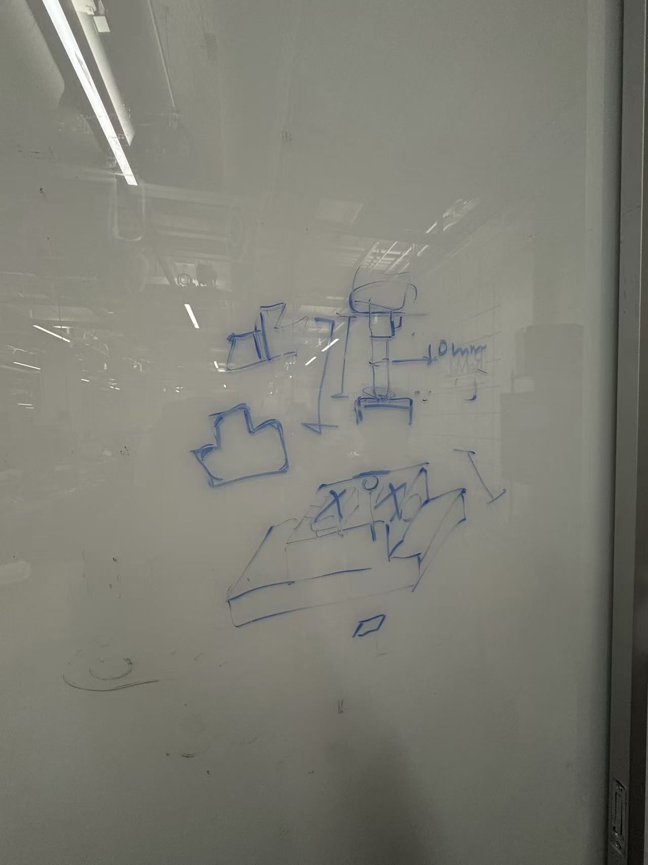
Early wearable kinematic capture iteration (V1)
Wearable Data Collection Device — early iterations
We developed a wearable glove device to capture finger joint movements, but early iterations were difficult to wear and failed to accurately track the complex, multi-axis kinematics of the thumb. I worked through multiple failure cycles, rapidly 3D printing new customized parts to improve the ergonomics and optimize the sensor placement for accurate data capture.
The thumb path was the recurring bottleneck: unlike the fingers, it couples roll and abduction in ways that are easy to average away in software if the mechanical coupling on the glove is sloppy. Each revision tightened tolerances between printed guides and strap anchors so joint axes stayed consistent across repeated donning and removal—the kind of repeatability we needed before any downstream controller could trust the joint angles.
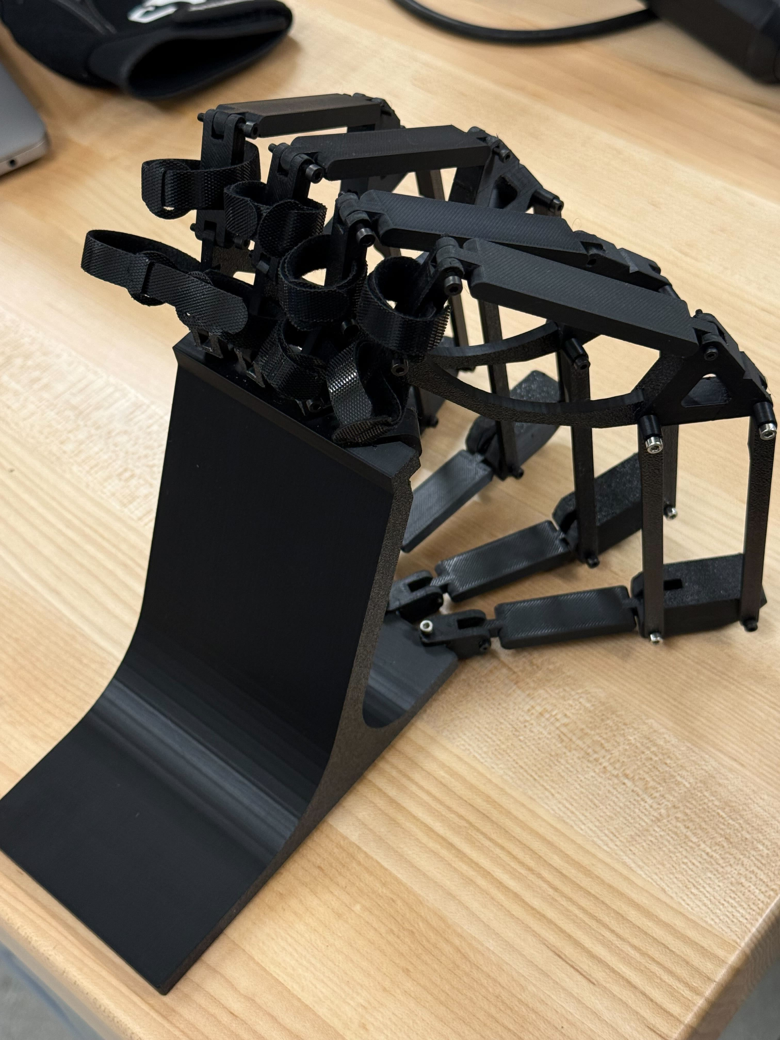
Wearable prototype closer to final ergonomics and sensor layout
Integrated wearable prototype
As the glove matured, the emphasis shifted from “does anything measure?” to “does it measure the same thing twice?” We routed sensing closer to the joints we cared about for inverse kinematics, trimmed bulk where it interfered with natural closure, and iterated strap geometry so subjects could maintain a relaxed neutral pose during long calibration captures without shifting the hardware on their hands.
This stage sat directly upstream of dataset quality: before we could argue about neural nets or filtering, the gloves had to stay mechanically repeatable minute-to-minute. That requirement drove a lot of mundane but critical choices—screw sizes that did not strip in PLA after ten swaps, cable exits that did not torque the PCB when the hand opened fully, and retention features that still cleared the palm during power grasps.
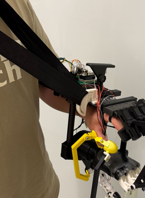
Alternate view of the integrated capture hardware
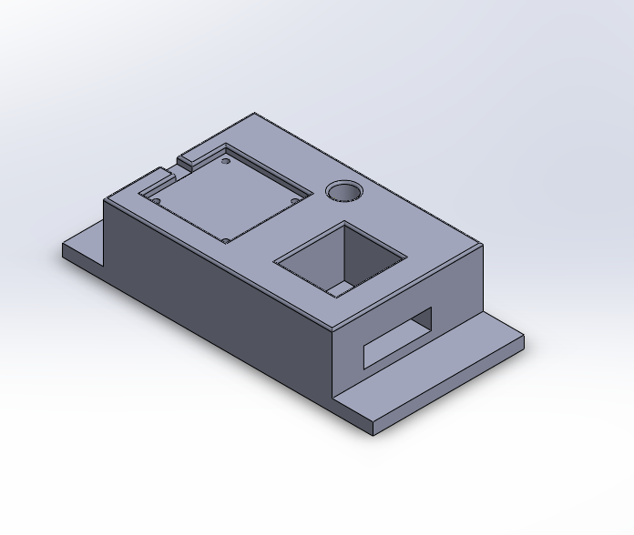
System integration snapshot
The later assemblies bundled sensing, routing, and anchors into a single mechanical story: printed shells carried PCB outlines, strain-relief features managed flex tails from moving joints, and anchor points stayed co-planar enough that calibration poses stayed identifiable on camera when we cross-checked portions of the pipeline.
This view also highlights how tightly coupled mechanical and electrical schedules became—every hole pattern on the printed frame eventually lined up with either a sensor carrier or a cable tie-down, so revisions were rarely “CAD-only”; they rippled into soldering order-of-operations and connector accessibility during debugging sessions.
Tactile sensing & calibration rigs
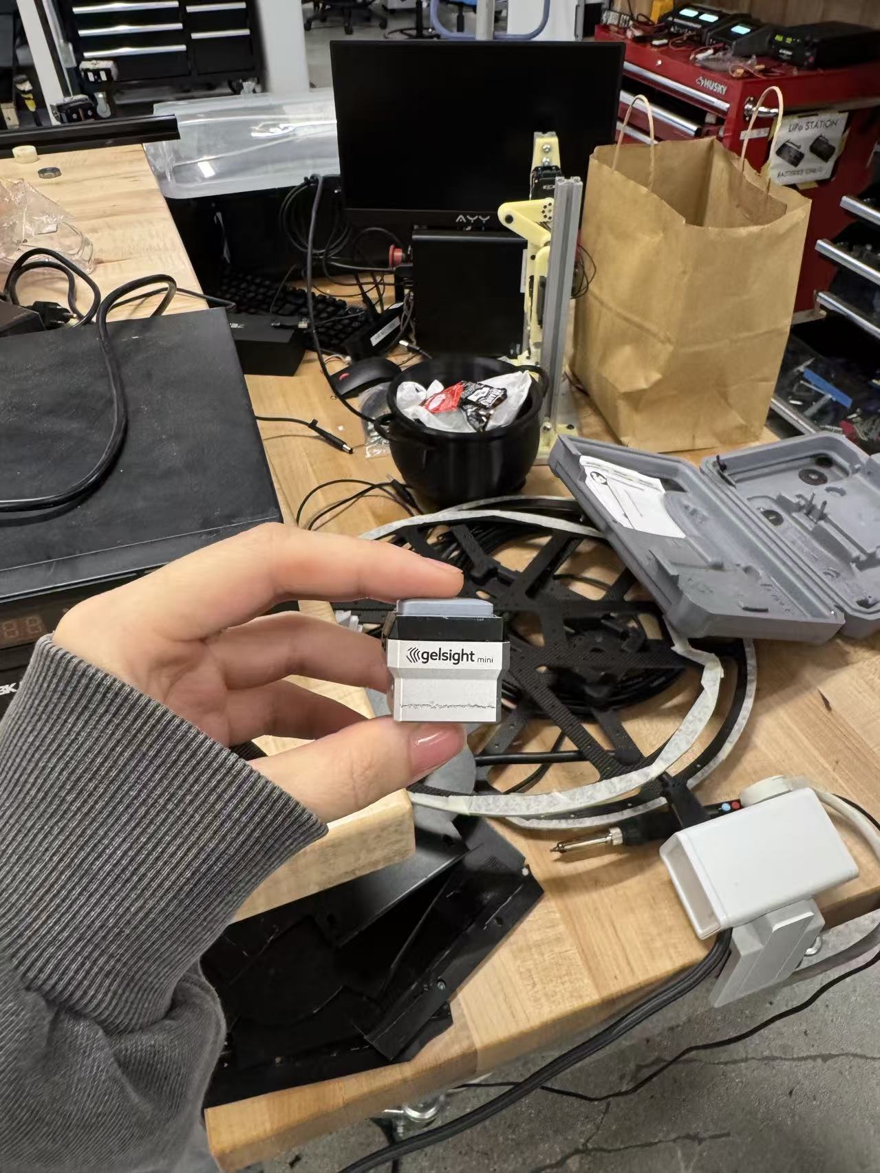
Tactile sensor hardware prior to calibration experiments
Sensor hardware focus
Before we trusted any automated motion platform, we isolated the tactile hardware itself: verifying interconnect integrity, conditioning electronics noise floors, and confirming that repeated seating against a probe produced distributions tight enough to benchmark comparably across days. Those checks informed how aggressively we could later automate scans without mistaking drift for material behavior.
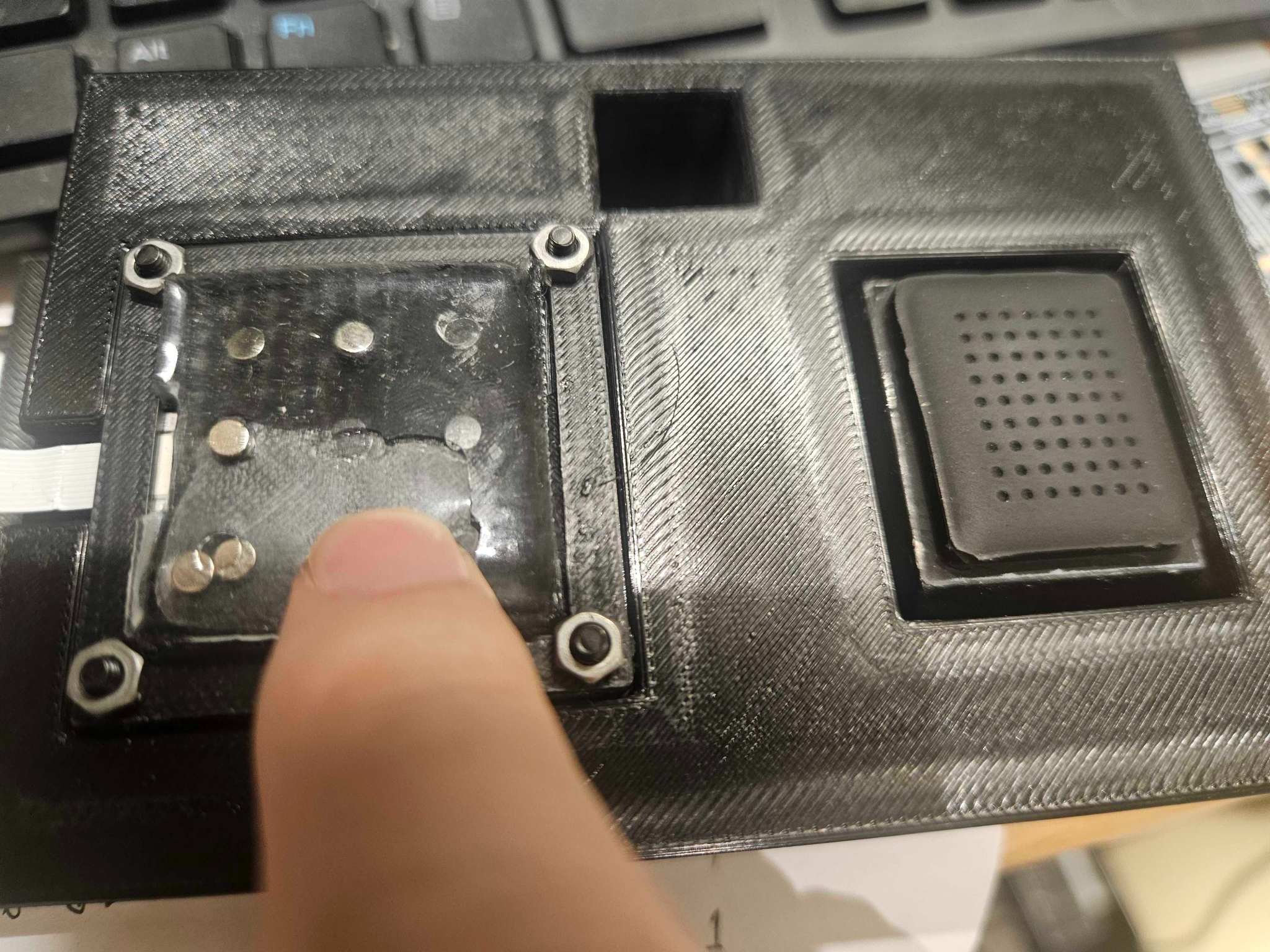
Calibration workflow documentation (process view)
Calibration workflow
Once sensors survived bench checks, we formalized a repeatable calibration choreography: fixture alignment, probe approach speeds, dwell times, and safe retraction so soft materials were not overstressed during repetitive characterization. Documenting the setup—rather than only the numbers—made it easier when another researcher needed to reproduce a dataset months later.
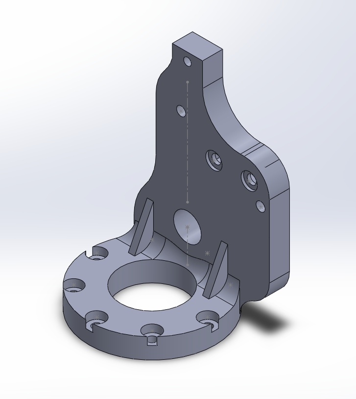
Gantry-mounted probe and custom brackets on printer XYZ axes
Printer gantry as a Cartesian rig
We initially struggled to get accurate, repeatable tactile sensor measurements using a standard robotic arm. To solve this, I repurposed a 3D printer's mechanical gantry. By designing and assembling custom mounting hardware, I utilized the printer's highly precise XYZ coordinate system to move our measurement tool, allowing us to capture much more detailed and accurate tactile readings.
This photograph emphasizes the mechanical narrative: brackets tied the probe assembly to an existing Cartesian frame we trusted, trading workspace envelope for repeatability and stiffness—often the right trade when characterization noise dominates exploration noise.
Complete tactile calibration rig in context
Tactile Sensor Calibration Rig — full setup
Stepping back, the full rig shows routing discipline as important as motion precision: grounded bundles away from encoder leads, staged cable loops that did not tug when the gantry hit limits, and anchoring that kept the tactile patch mechanically referenced to the probe path across long sessions.
That context matters because tactile datasets are sensitive to unseen degrees of freedom—small slips between fixture and sensor housing show up as phantom hysteresis. We iterated bracket stiffness until scans looked stable before touching software filtering.
Electrical integration & prototyping
Bench soldering, rework, and harness integration
Electrical Integration & Prototyping
I managed the physical electrical integration for the project, performing the majority of the soldering for the sensor wiring and custom control boards. This ensured a reliable bridge between our data collection software and the physical 3D-printed hardware.
Practically, that meant planning rework-friendly layouts: connector orientation where heat-shrink access stayed possible after mounting, strain relief that survived glove flex cycles, and grounding strategy so analog front ends did not pick up motor PWM noise when we later drove nearby channels during integrated demos.