


Project Overview
Autonomous S'more-Making Mobile Manipulator
The Challenge
The goal of this capstone project was to design and build an autonomous mobile manipulator robot capable of preparing a s'more within a single, continuous workflow. The system was required to autonomously maneuver through an obstacle course, stop precisely within a 1-inch clearance of a finishing line, and transition into a manipulation phase. From there, the robot had to visually identify a marshmallow from multiple objects within a 12-inch radius, retrieve it, transport it to the chassis, and toast it using a custom electrically heated mechanism integrated into the gripper. The entire operation had to be executed autonomously within a strict 30-second time limit.
My Role: Project Manager & Hardware Lead
As the Project Manager and Hardware Lead, I directed the complete hardware lifecycle—from initial white-boarding and CAD modeling to physical prototyping, assembly, and rigorous troubleshooting. I was responsible for coordinating our engineering team, distributing tasks, and aligning everyone's diverse design ideas into a single, cohesive mechanical direction. By bridging the gap between mechanical structures, electronics, and software, I ensured the physical hardware could reliably support the complex autonomous tasks.
Hardware Architecture & Design
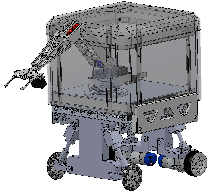
To achieve our functional requirements, I oversaw the integration of five primary subassemblies: the chassis-electric base, independent front and back wheel suspensions, a sliding protective enclosure, and the arm-turntable interface.
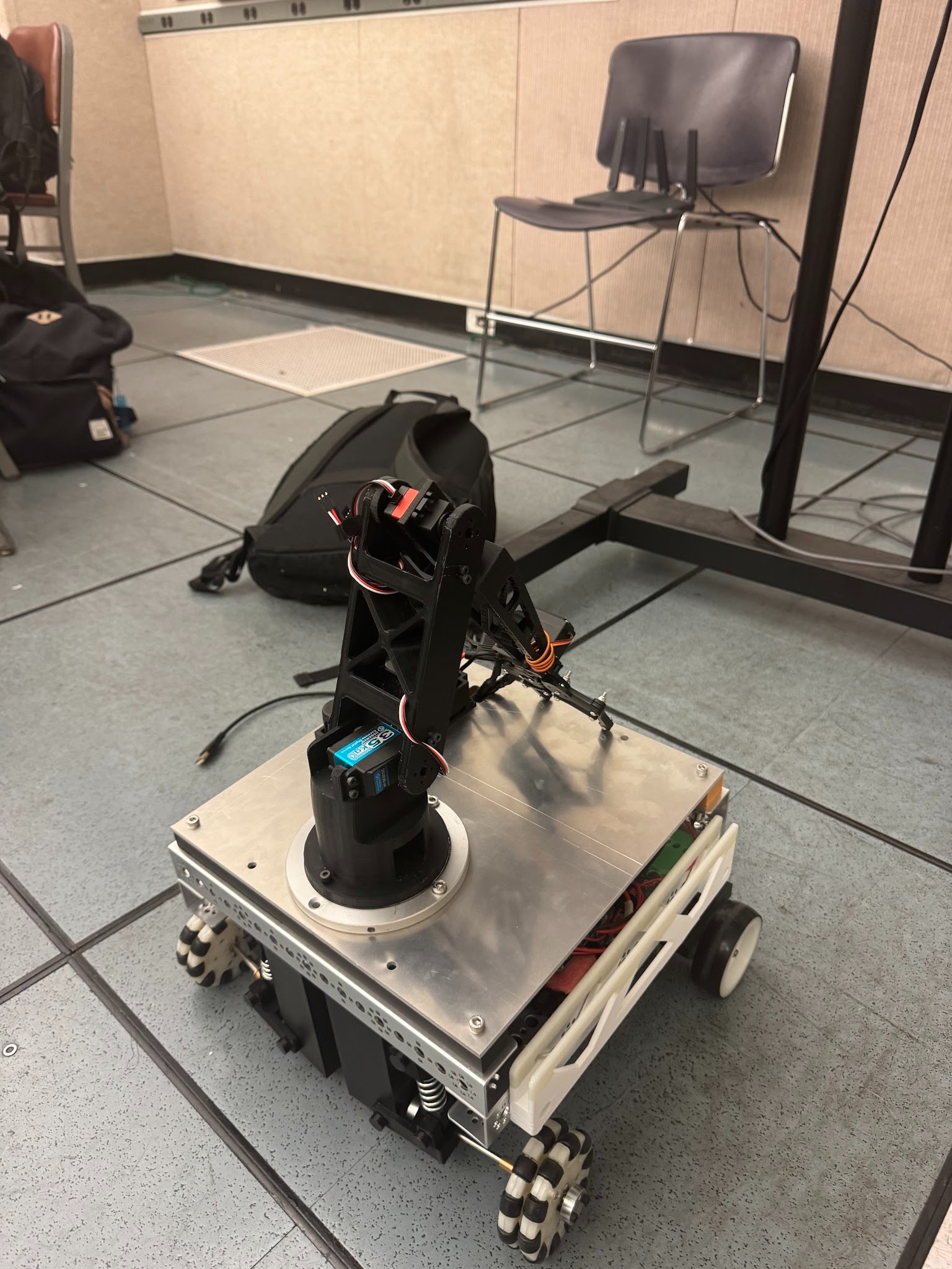
Hardware integration and assembly detail
Robust Chassis & Suspension
The mobile platform was built around a rigid 6061 T6 aluminum main chassis plate. It featured a double wishbone linkage suspension system equipped with compression springs designed to absorb kinetic energy, allowing the rover to survive a 1-meter drop test and an impact test from a basketball without losing functionality.
Two-link planar manipulator on the platform
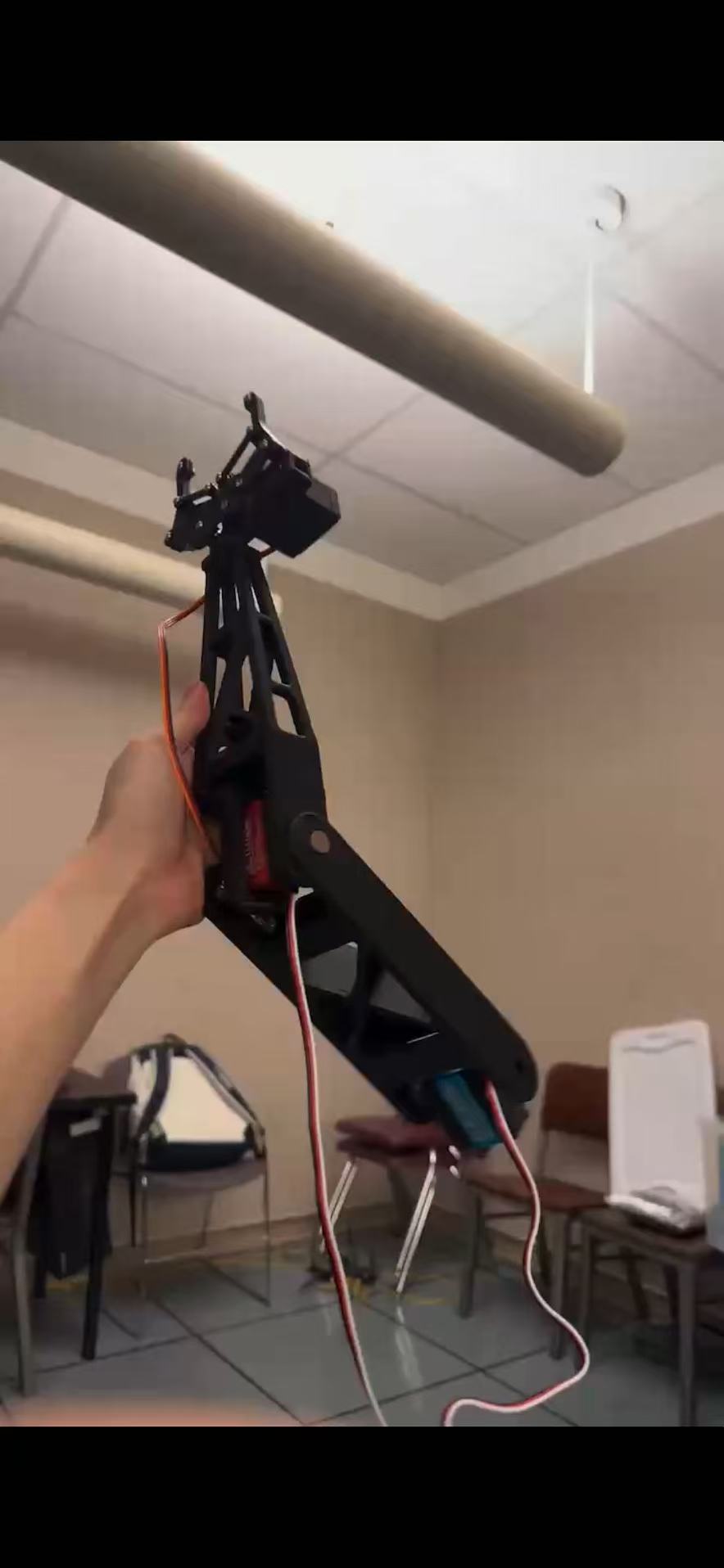
Manipulator Arm Dynamics
I heavily focused on the manipulator's structural design, engineering a two-link planar mechanism to satisfy a 12-inch vertical workspace. To minimize the resistive torque acting on the shoulder joint, I designed the links with a hollow interior and a tapered profile, successfully shifting the center of mass closer to the pivot while maintaining the moment of inertia required to resist bending.
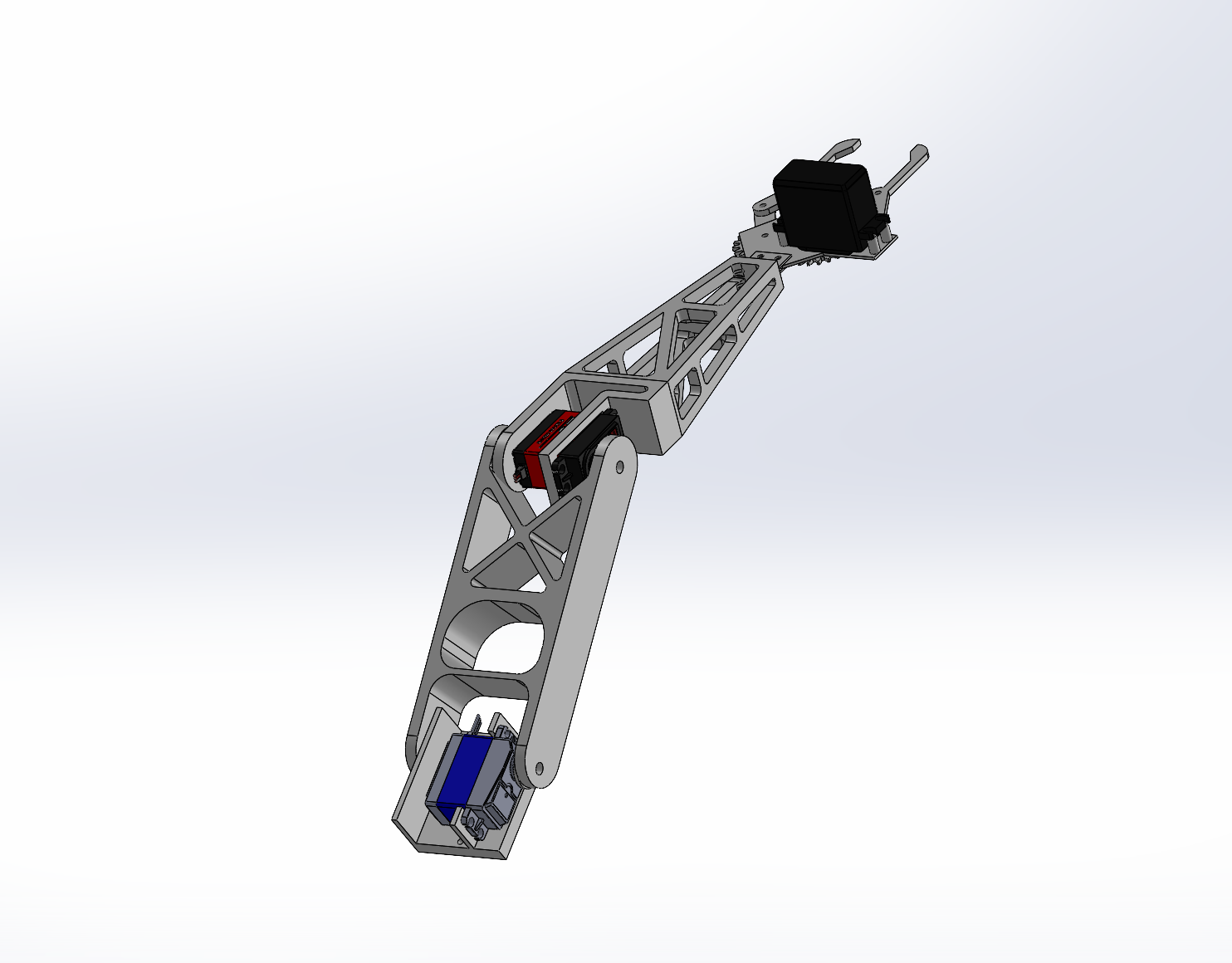
Arm assembly (CAD): two-link planar mechanism
Manipulator CAD
The CAD assembly shows the hollow, tapered links and the shoulder pivot layout used to keep mass close to the joint while preserving bending stiffness over the 12-inch workspace.
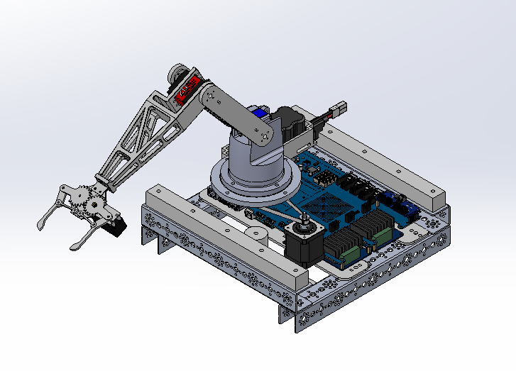
Lazy susan bearing interface (CAD)
Rotational Stability
The arm was mounted to a 4-inch lazy-susan bearing with a static load capacity of 500 lbs. This centralized the structural interface at the top plate, ensuring that overturning moments generated by the arm were effectively transferred down through the chassis to prevent tipping during the manipulation phase.