


Project Overview
Autonomous Trash-Collecting Vehicle
The Challenge
The objective of this project was to design and assemble a mobile robotic vehicle to remove small obstacles and debris from urban streets. The system required a fully integrated vehicle platform with independent propulsion and steering, paired with a 3-DOF manipulator arm. The robotic arm needed two revolute joints for angular positioning and one prismatic joint for linear extension, allowing the end-effector to reach into narrow or constrained areas for collection operations.
My Role: Hardware & Mechanical Design Lead
I was primarily in charge of the physical hardware, managing the mechanical design, assembly, and rigorous troubleshooting of the system. I specifically architected the vehicle's steering mechanism and took the lead on iterating our 3D-printed components. By analyzing structural failures under dynamic loads, I continually refined our CAD models and printing parameters to overcome the material limitations of PLA and ensure the physical vehicle could perform reliably in the real world.
Hardware Architecture & Design
To ensure smooth navigation and reliable object retrieval, I focused on structural rigidity and precise mechanical linkages across the vehicle and the arm:
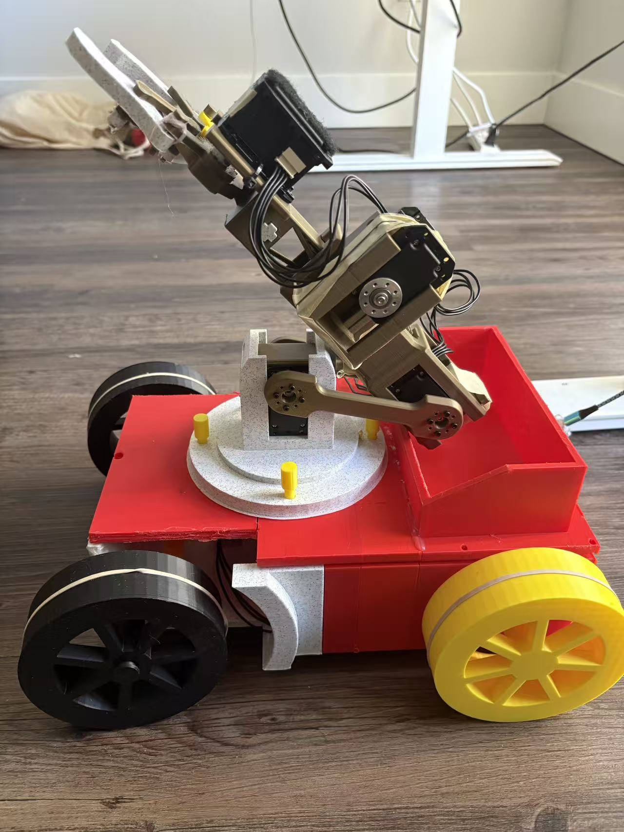
Full vehicle: propulsion, steering, and manipulator integrated
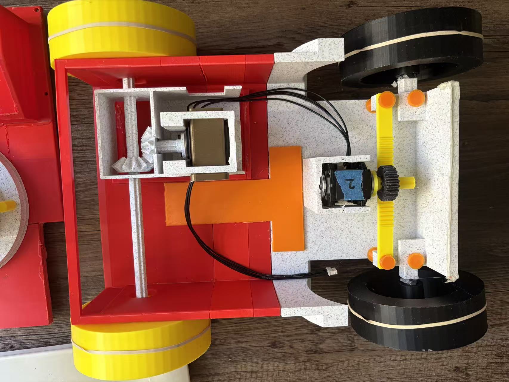
Ackermann Steering System
I designed a custom rack-and-pinion steering assembly driven by a central, high-torque servo motor. I integrated Ackermann steering geometry into the tie rods and steering knuckles so that the inner wheel rotates at a steeper angle than the outer wheel during turns. This prevented tire scrubbing and reduced the load on the servo during tight maneuvers.
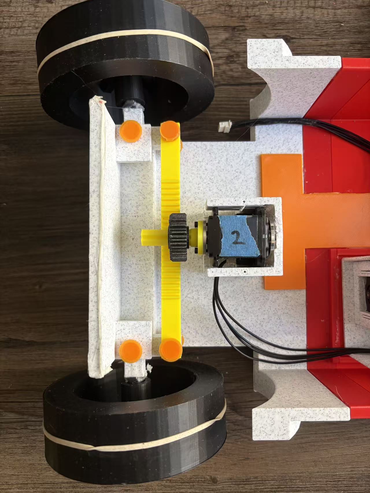
Steering linkage at the wheel
Steering hardware detail
Tie rods, knuckles, and wheel-side hardware implemented the Ackermann layout on the physical chassis—where print tolerance and backlash had to be tuned so the servo did not stall in hard turns.
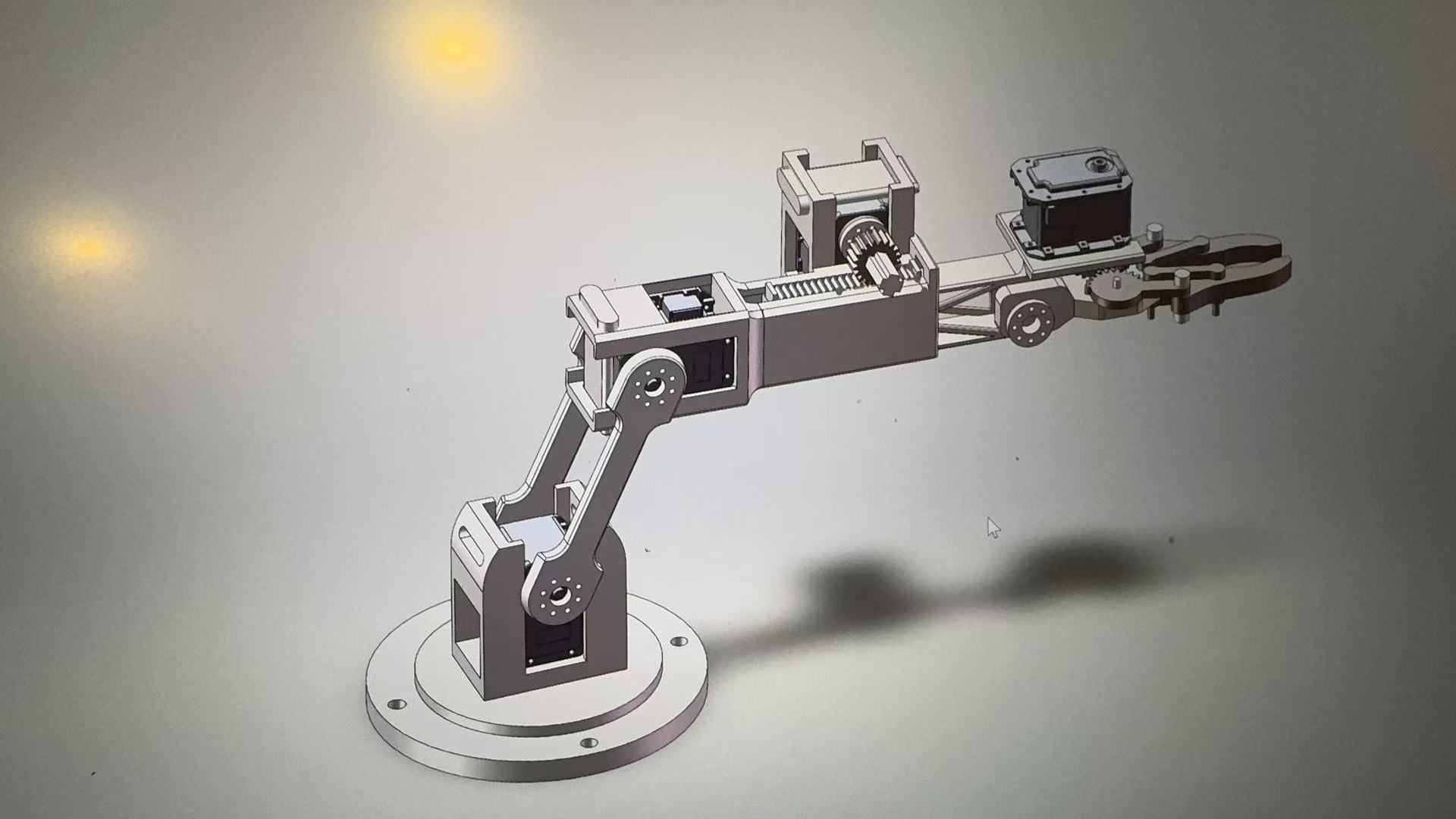
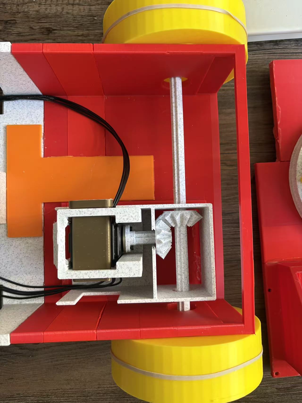
R-R-P manipulator CAD (revolute-revolute-prismatic)
3-DOF Manipulator Evolution
I engineered the R-R-P (Revolute-Revolute-Prismatic) arm structure to maximize our workspace. When our initial worm-gear prismatic joint failed due to 3D printing tolerance limitations, I quickly redesigned it into a robust rack-and-pinion linear extension mechanism to guarantee reliable meshing.
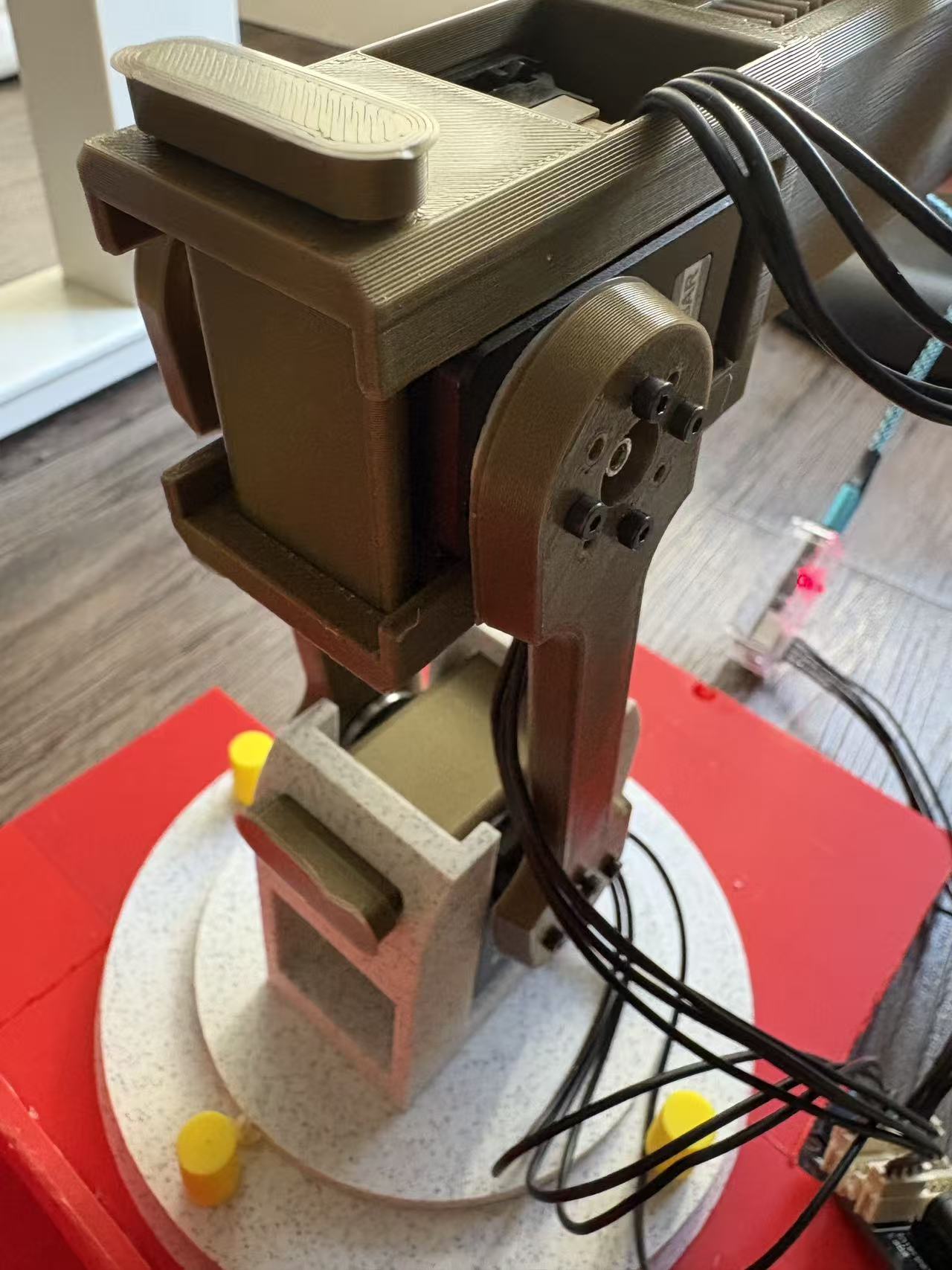
Physical arm on the vehicle during bring-up
Prototype build
The assembled arm had to survive repeated extension cycles and side loads while we iterated joint preload, fastener torque, and print orientation before locking the rack-and-pinion prismatic stage.
Arm motion and workspace testing
Arm testing (video)
Video capture of the arm under motion helped verify range, interference, and whether printed teeth stayed engaged through the prismatic stroke.
Failure modes on early prismatic / worm-gear concepts
Failure analysis (video)
Documenting the failing process made it clear where tolerance stack-up and tooth engagement were insufficient—directly informing the rack-and-pinion redesign and print settings.
Gearbox / transmission hardware
Iterative Structural Reinforcement
During early testing without PID control, abrupt oscillatory motions caused our keyed-shaft joint connections to fracture. I troubleshot this by redesigning the linkages to mount directly to the motor flanges for a more rigid connection. I also increased wall thicknesses, added reinforcement ribs, and fine-tuned extrusion parameters to ensure our FDM-printed parts could survive high torque loads.
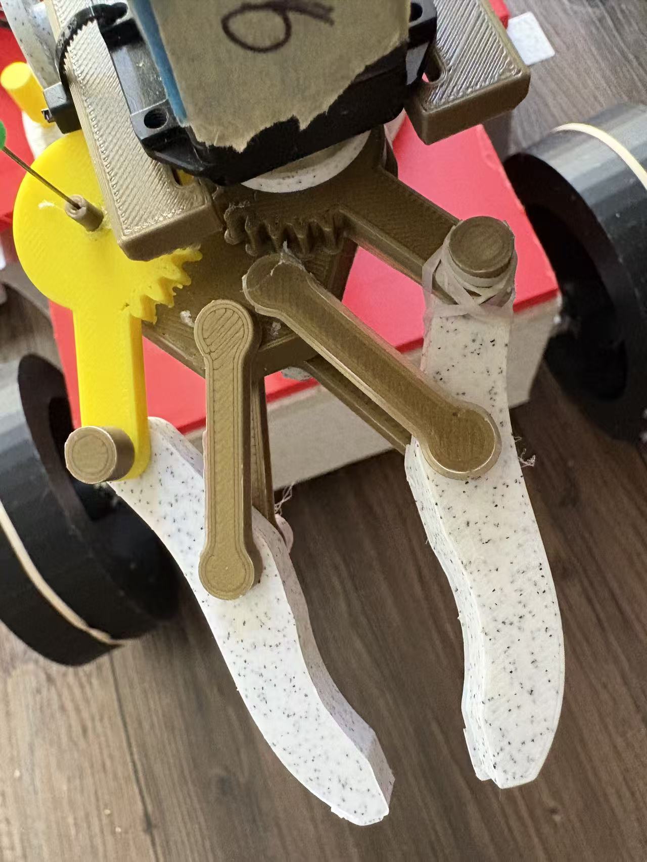
Gripper / end-effector interface
End-effector hardware
Gripper-side parts saw high shock during contact; rib layout and flange-mounted interfaces reduced stress concentrations compared to keyed-shaft joints alone.
Printed housings with thicker walls and ribs
Printed enclosures
Enclosures and brackets were revised to add material only where moment and bearing reactions demanded it—balancing print time with stiffness for the chassis and arm bases.
Full-vehicle integration testing (two runs)
Vehicle-level testing (video)
On-vehicle runs exposed the dynamic loading that fractured keyed joints and motivated flange-mounted linkages, ribbing, and slicer parameter changes across the platform.
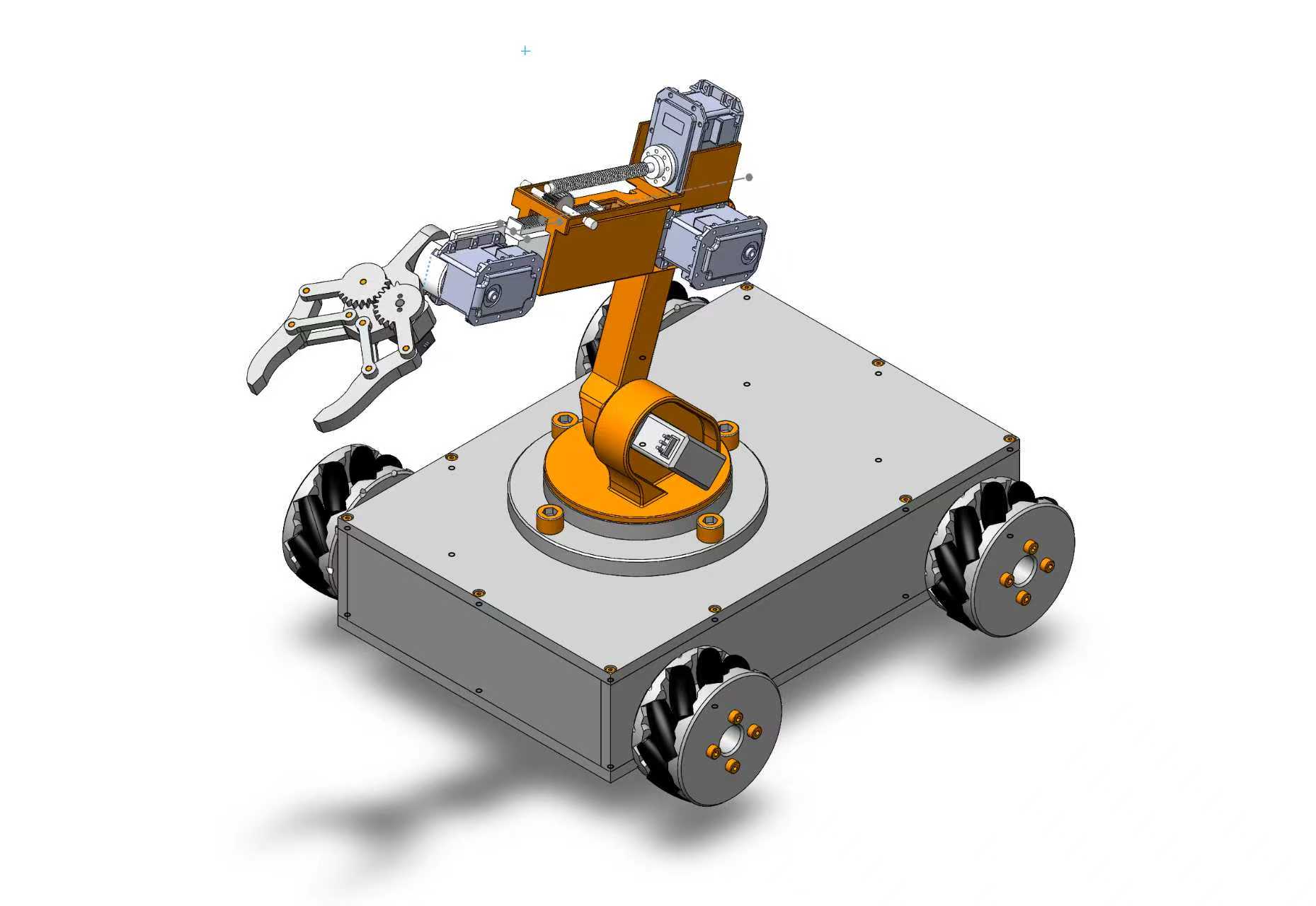
CAD overview (same assembly as project index / hero)
System-level CAD
This top-level CAD matches the portfolio introduction image: chassis, steering package, and manipulator in one revision used to align the team on interfaces before fabrication.